Learn Ladder Logic
If you want to learn PLCs, you absolutely need to learn Ladder Logic. I've got an epic post for you today to tell you everything you need to know to get started on your PLC training journey by learning Ladder Logic.
Here's what I've got in store for you:
- An Introduction to PLC Ladder Logic (3 most important instructions)
- Video Walk-Through of a real Ladder Logic program in Studio 5000 (relay-type instructions, timers, counters and more)
Introduction to Ladder Logic
Ladder Logic is a programming language that PLCs have been using in some form since the ’70s. Now, it’s gone through some changes over the years but is still very popular and heavily used in manufacturing and industrial automation.
Nowadays, there several other programming languages available for PLCs/PACs but Ladder Logic is still really popular for a few reasons.
- It's been the industry standard for many years.
- It’s easy to learn and implement because it works like electrical control circuits (something engineers, techs, electricians already understand to some degree).
- And probably, the biggest reason...it’s VERY easy to troubleshoot.
Most people who are reading this already have seen PLC Ladder Logic, but let’s look at the 3 most important Ladder Logic Instructions. They are the the XIC (examine-if-closed), XIO (examine-if-open) and OTE (output-energize).
Here’s what these ladder logic symbols look like…
(XIC)
----| |-----
(XIO)
----|/|-----
(OTE)
----( )-----
If you’re familiar with control circuits at all these should look familiar. The XIC is intended to look and function like a normally-open contact, the XIO is intended to look and function like a normally-closed contact and the OTE is supposed to function as the coil of a relay.
If you’re new (or rusty) to electrical circuits, let me break down how these instructions work.
The XIC is normally off and not allowing “power” to flow through it to any outputs, but when it is turned on (for example if it’s addressed to a push-button input) then it allows “power” to flow to any other Ladder Logic elements to the right of the input.
The XIO, on the other hand, does just the opposite. It normally allows “power” to flow through it to the other Ladder Logic elements and instructions to the right, but when the input is turned on the XIO opens, interrupting the “power flow”.
The OTE is what is used in programs to actually turn stuff on. In other words, you use the OTE to turn on your motors, lights, open/close valves, etc. It’s the output instruction that you use to command your outputs to operate.
These three instructions are at the heart of every Ladder Logic program. With just the XIC, XIO and OTE you can create many simple and complex logic programs.
Two other really important instructions are the Timer and Counter instructions. Which I’ll talk more about below. But first check out the list of resources I put together if you want to learn even more about Ladder Logic:
Get the FREE Resource Bundle
Ladder Logic Video Walk-Through
Prefer to read it? Go Ahead...
This video is all about ladder logic.
Here I have a program open with some basic ladder logic instructions so that you can see how these instructions actually work.
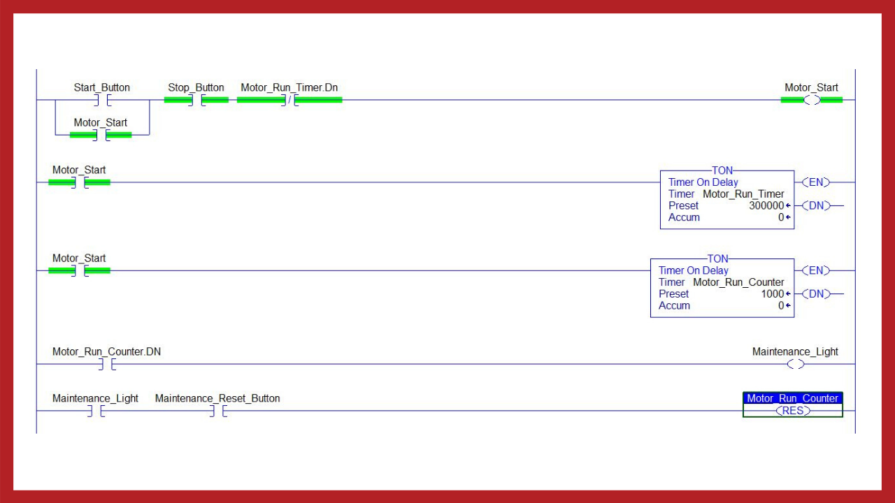
So, we have five rungs of logic here. Very simple program but if you’re new to ladder logic then this might seem kind of intimidating, but don’t worry I’m going to walk you through each rung and show you how all this works.
Project
So first, I just want to make a few comments about the project I have set up here. Notice, this is Studio 5000 Logix Designer and the project is set up with an Emulate controller and I have one IB16 discrete input module and one OB16E output module in the rack.

Rung 0: XIC, XIO, OTE, Latching Circuit
Now let’s get into the Ladder Logic here and start with rung 0: here we have simple rung with a few XICs (which function like normally open contacts) and one XIO (Which functions like a normally closed contact) and then we have one OTE which functions as a relay coil.
Notice how the START_PB tag has an address underneath. The address is for local rack as you can see it says local, and the “1” is for slot 1: look down here at the slot number 1 and see it’s the IB16, which is the input module, and then data.0 which means this is the first or the zeroth, if you will, input channel of the IB16 module.
Next, we have the STOP_PB tag in a XIC which is addressed to slot 0 channel 1. By the way, these addresses are set up by using what’s called tag aliasing. Which basically means you give the address an alias or tag name which more descriptive and convenient to work with. If you’re interested in learning more about aliasing check out our free training on tag aliasing linked below.
And then all the way on the right we have a OTE instruction with the MOTOR_START_RELAY tag and it is addressed to slot 2 and channel 0.
Now let’s come back here to the left side again. This is what is called a seal-in or latching ladder circuit. So this part of the logic won’t engage until we first we engage the output with the upper part of the circuit.
But as you can see here, there’s the MOTOR_START_RELAY tag again but this time it’s being used in a XIC, so if you’re not familiar with how a seal-in circuit works, here’s a quick explanation: when the start button is pressed it activates the motor start relay which then closes this XIC or normally open contact and provides a second path to energize the MOTOR_START_RELAY coil or OTE, so that when the start button is released the MOTOR_START_RELAY output stays engaged.
Now, this next item here is what will be in charge of stopping the motor or interrupting the ladder circuit.
This is an XIO which, again, functions like a normally closed contact. And when this tag, the Motor_Running_Stop_Timer.DN becomes true this instruction will open like a normally closed contact would and it will interrupt the circuit or break the seal such that to start the motor again you’d have to press the start button again.
Now, one last thing about this rung, we haven’t really talked about the STOP_PB button. So here are two questions to consider.
- First, why is the STOP_PB up here instead of down here with the timer done bit since both would be used to interrupt the circuit?
- Also, why is it an XIC instead of an XIO like the Motor_Running_Stop_Timer.DN bit?
Ok, for the first question, why is it in the middle of the rung rather than just the seal-in area?
Well, having the STOP_PB here allows it to not only interrupt the seal-in circuit path but also to block the START_PB from starting the motor. Whereas the Motor_Running_Stop_Timer.DN bit can only interrupt the seal-in circuit.
Ok, so the other question is why did I use a Normally-Open contact (or XIC)? This has to do with how the STOP_PB contact is wired to the input module. Now obviously this contact needs to be closed in order to allow the motor to start. So first I’ll tell you why it needs to be like this and then I’ll tell you how this contact needs to be wired to the input module.
So here’s why: one of the concepts that we have developed in industrial controls is the idea of making a circuit fail-safe. In other words designing your controls in a such a way that if a control circuit or device fails, the equipment that it controls will shut down, rather than keep running without a way to shut down.
So, what we want for our stop button control is that if the wires or the push-button fails for some reason or a wire becomes loose and loses the connection we want this logic to shut off the motor. And that’s for two reasons. The primary reason is that we don’t want to lose our stop control of the motor because it may need to be stopped for safety purposes and the second related reason is that we wouldn’t know it failed until we tried shutting the motor down if it was not wired in a fail-safe way.
Ok, so that’s why it’s important for the stop button to be wired in a fail-safe way. So what exactly is the correct way to wire it to the input? Well, it’s really simple actually, all you do is wire a normally-closed contact to the PLC input for this tag. So the actual physical contact that’s wired will be the opposite of this instruction.
So, if the input is normally closed then that means this tag will normally be on, or 1. So if the stop button is pressed or if the button fails or the wires breaks or loses its power source then this input will turn off and our rung will become false and blocked from operating.
Ok, so that was a nice little tangent, but I wanted you to be aware of the importance of fail-safe circuits like this and how they interact with your PLC logic.
Rungs 1-2: Lights
Moving on to the next rung. These next two rungs are very simple. Basically we use the MOTOR_RUNNING input to either turn on the MOTOR_RUNNING_LIGHT or turn on the MOTOR_STOPPED_LIGHT output.
So if the MOTOR_RUNNING input is on we turn on the MOTOR_RUNNING LIGHT and if the MOTOR_RUNNING input is off we turn on the MOTOR_STOPPED_LIGHT. Now keep in mind that for this to work right we are assuming that the MOTOR_RUNNING input is contact is wired to the PLC input as a normally open contact, right? Unlike the STOP_PB we discussed a minute ago.
Rung 3: Timer
Alright, moving on to the next rung let’s quickly discuss timers/counters! We won’t go into too much detail here for the sake of time but if you need to learn timers/counters well and get some practice programming with them you definitely should join our PLC membership, myPLCtraining Academy.
Ok, so Rung, 3 has a TON timer. TON is short for "timer-on delay". And it has 30000 in the preset field which means it’s set for 30000 milliseconds or 30 seconds. So after the motor has run for 30 seconds we interrupt the motor start relay and stop the motor.
Rung 4: Counter
Next, we have a CTU counter which is a count-up counter. And this just counts 1 for every time the MOTOR_RUNNING input goes from off to on. So once this counter reaches 100 we go to the next rung and see that the PLC will turn on the MOTOR_MAINTENANCE_LIGHT and reset Motor_Rung_Count to zero using this RES instruction. RES is for reset.
Furthermore, we are using latching logic here to latch in the MOTOR_MAINTENANCE_LIGHT output until someone presses the MAINTENANCE_RESET_PB.
Now before we wrap up this PLC training lesson let’s simulate starting the motor one time.
So here we are online with a Logix Emulate controller running the program. I have some simple simulation logic that will turn on the MOTOR_RUNNING input a couple of seconds after turning on the start relay.
So I’m just going to toggle the START_PB input tag and we can see the MOTOR_START_RELAY output toggles on and then a couple of seconds later the MOTOR_RUNNING input turns on and we can see the timer begins timing and we have a count of 1 in our counter.
We will wait untill the timer stops the motor…
And there you have it. 30 seconds later the timer interrupted our MOTOR_START_RELAY latching rung and shuts down the motor.
Ok, that’s it for this walk-through video of Ladder Logic. Hopefully. you learned something and are a little closer to becoming a confident PLC programmer.
Next Steps
If you’re really serious about speeding up the process toward becoming a confident PLC programmer then check out our membership, myPLCtraining Academy ( there’s a link below) where we have step-by-step PLC training courses to become confident with Allen-Bradley PLC programming and troubleshooting and soon we will be adding an HMI design course to the membership.
And in the meantime check out the resource list I put together for you if you want more PLC training and specifically to learn more about Ladder Logic.
Get the FREE Resource Bundle
Enjoy!
Get the Free PLC Cheat Sheet
PLCs are really not that complicated. If you are new to PLCs or just looking to get a better handle on how they work, check out this free cheat sheet, called the "Motivated Electrician's Guide to Understanding ANY PLC System."


New to PLCs?
You can breeze through this cheat sheet in about 10 minutes and get a solid understanding of the big picture of how PLCs work. Perfect place to start.
Recent Posts