Beginner's Free PLC Training Part 1 of 4: Introduction to PLCs
If you've been wanting to get into industrial automation and been looking for basic PLC training, but you are not sure where to start, then this Beginner’s Free PLC Training blog series has been written for you!
After you’ve read this 4-part free PLC training series you should be able to identify the primary components of a PLC system and have a basic understanding of the purpose and function of PLCs (and PACs).
When you complete this series, you should be ready to begin learning PLC programming. If you have any questions about this content, please feel free to comment on the post. So, without further delay, let’s jump right into our introduction to PLCs!
Beginner’s Free PLC Training Series Outline
- Introduction to PLCs
- PLC Processors (CPU)
- PLC Inputs and Outputs (I/O)
- PLC Ladder Logic
Programmable Logic Controllers (PLCs) are small industrial computers with modular components designed to automate customized control processes. PLCs are often used in factories and industrial plants to control motors, pumps, lights, fans, circuit breakers and other machinery. To understand the purpose of PLCs better, let’s look at a brief history of PLCs.
History
Industrial automation began long before PLCs. In the early to mid 1900s, automation was usually done using complicated electromechanical relay circuits. However, the amount of relays, wires and space needed to create even simple automation was problematic. Thousands of relays could be necessary to automate a simple factory process! And if something in the logical circuit needed to be changed? Oh boy!
NOTE: On a basic level, electromechanical relays function by magnetically opening or closing their electrical contacts when the coil of the relay is energized. The are very useful devices and still play a major role in industrial automation (for a more in-depth lesson on electromechanical relays check out this post).
In 1968 the first programmable logic controller came along to replace complicated relay circuitry in industrial plants. The PLC was designed to be easily programmable by plant engineers and technicians that were already familiar with relay logic and control schematics. Since the beginning PLCs have been programmable using ladder logic which was designed to mimic control circuit schematics. The ladder diagrams look like control circuits where power is flowing from left to right through closed contacts to energize a relay coil.

Ladder Logic Example
As you can see, ladder logic looks like simple control circuit schematics where input sources like switches, push-buttons, proximity sensors, etc are shown on the left and output sources are shown on the right. The ability to program complicated automated processes with an intuitive interface like ladder logic made the transition from relay logic to PLCs much simpler for many in the industry.
Although, the first PLCs were very limited in their memory and speed capabilities, they quickly improved over the years. The presence of PLCs helped simplify the design and implementation of industrial automation. For more on the history of PLCs, see this great little article from AutomationDirect here.
How Do PLCs Work?
PLCs can be described as small industrial computers with modular components designed to automate control processes. PLCs are the controllers behind almost all modern industrial automation. There are many components to a PLC, but most of them can be put in the following three categories:
- Processor (CPU)
- Inputs
- Outputs
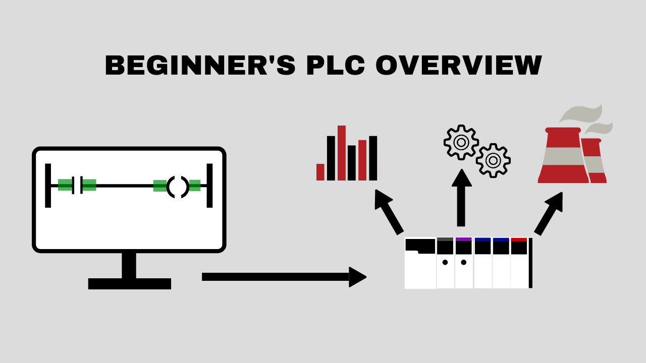
PLCs are complex and powerful computers. But, we can describe the function of a PLC in simple terms. The PLC takes inputs, performs logic on the inputs in the CPU and then turns on or off outputs based on that logic. We will get into more detail later but for now, think of it like this:
- The CPU monitors the status of the inputs (ex. switch on, proximity sensor off, valve 40% open, etc.)
- The CPU takes the information that it gets from the inputs, performs logic on the inputs
- The CPU operates the outputs logic (ex. turn off motor, open valve, etc.)
See the flowchart below for a visual representation of the steps above.

PLC Function Flowchart
Let’s use a familiar example to illustrate how PLCs work. Your dishwasher. Many dishwashers have microprocessors that function similarly to PLCs. The dishwasher has inputs, outputs and, of course, a CPU. Some of the inputs into the dishwasher controller would be the buttons on the front, the water sensors and the door switch. Some of the dishwasher outputs would be the water valves, the heat elements and the pumps. Now let’s think about how the dishwasher uses those different components.
NOTE: Remember, the CPU is the processor in the dishwasher that is programmed to make all the decisions we will see below. This is just like a PLC processor (CPU) which makes logical decisions based on input status.
- User pushes the cycle mode button (input detected)
- User pushes the start button (input detected)
- CPU verifies that the door is closed (input detected)
- Fill valve opens and the dishwasher begins filling with water (output activated)
- CPU waits until proper water level is reached (input detected)
- Fill valve closes, and water flow stops (output activated/de-activated)
- Heating element is turned on (output activated)
- CPU waits until proper water temperature is reached (input detected)
- Soap dispenser opens (output activated)
- Water pump turns on to force water through sprayers (output activated)
- CPU begins timing depending on cycle type (logic timer activated)
- Water pump turns off (output deactivated)
- Heating element is turned off (output deactivated)
- Drain valve opens and the dishwasher begins draining the dirty water (output activated)
- CPU waits until it detects the water level to be low enough (input activated/de-activated)
- Drain valve closes (output activated/deactivated)
- Fill valve opens again to rinse dishes (output activated)
- Water pump turns on to force water through sprayers (output activated)
- CPU begins timing (logic timer activated)
- Water pump turns off (output deactivated)
- Drain valve opens and the dishwasher begins draining rinse water (output activated)
- CPU waits until it detects the water level to be low enough (input activated/de-activated)
- Drain valve closes (output activated/deactivated)
- Heating element turns on to heat the air inside the dishwasher and dry the dishes (output activated)
- CPU waits until proper interior temperature is reached (input activated)
- CPU begins timing (logic timer activated)
- Heating element is turned off (output activated/deactivated)

Dishwasher Control Graphic
Discrete and Analog I/O
Inputs and outputs are often abbreviated with the term “I/O”. In the the dishwasher example above, we treated every input and output as a discrete or digital signal.
Discrete signals are signals that can only be on or off. These are the simplest and most common type of I/O. In our example we did not use any analog I/O.
Although, there may be some use of analog I/O within a dishwasher control system, I wanted to keep this example simple.
With analog signals, instead of only on/off or open/closed possibilities, you may have 0 - 100%, 4 - 20mA, 0 - 100 degrees Celsius, or whatever it is you measuring as an input or driving as an output. We will cover this in more detail in part 3 of the Beginner's Free PLC Training series.
PLC or PAC?
You may have heard of the Programmable Automation Controller (PAC). The term was first coined by the market research firm ARC in 2001 to differentiate the original PLCs from the newer, more powerful, more flexible controllers that were entering the market. There is disagreement about the definition differences between PAC and PLC, and often the terms are used interchangeably in the industry. I often use the terms interchangeably myself. This article, here, from Control Engineering may help you understand the differences between PLCs and PACs. In my opinion PACs are always the better choice unless the system is very simple and minimizing cost of the project is vital. The modern user interface, extra power and memory of most PACs make them easily superior to most PLCs.
Allen-Bradley, one of the current leaders in industrial automation, is actually phasing out their PLC lines such as the PLC-5 and instead focusing on their PAC lines such as ControlLogix and CompactLogix. Personally, I think this is a great move. Among the many other benefits of the PAC, the user-friendliness of Rockwell’s RSLogix 5000/Studio 5000 Logix Designer (programming software for ControlLogix/CompactLogix PACs) far surpasses the older RSLogix 5/500 software (programming software for the PLC-5 and SLC500).
Having experience with both PLCs and PACs is important for everyone interested in working with industrial automation. However, PACs are the future and where you will spend most of your time as industrial automation engineer/technician.
Conclusion
Now you should you have a better understanding of what PLCs are, their history, and how they work. In Part 2 of this series, we will look at the PLC controller (CPU) in more detail. So be sure to tune in for that!
Click here for Part 2 of the Beginner's Free PLC Training Series
P.S. Interested in learning more about our online PLC training course? Check out our course inside myPLCtraining Academy.
Get the Free PLC Cheat Sheet
PLCs are really not that complicated. If you are new to PLCs or just looking to get a better handle on how they work, check out this free cheat sheet, called the "Motivated Electrician's Guide to Understanding ANY PLC System."


New to PLCs?
You can breeze through this cheat sheet in about 10 minutes and get a solid understanding of the big picture of how PLCs work. Perfect place to start.
Recent Posts