Intro to Function Block Diagram - Studio 5000 Logix Designer
In this blog post and video, we are continuing to help you toward becoming a confident PLC programmer by introducing the programming language called Function Block Diagram (FBD) inside Studio 5000 Logix Designer...
But before we get into this video, if you want some structured training courses and support to help you become a confident PLC programmer, then check out our membership called, myPLCtraining Academy.
Ok let’s get into this.
Function Block Diagram
This can be really useful when you have multiple machines that all have the same inputs and/or outputs available to the PLC controller.
Check out the video, transcript and screenshots below.
Intro to FBD - Studio 5000 Logix Designer
Prefer to read? Go ahead...
Hey guys, it's Stephen Gates here from myPLCtraining.com, with another video, to help you get confident with PLCs and become a confident automation professional.
This video is going to be all about function block diagram or FBD. And before we get into the video, I'm want to let you know that we have created a free resource. You can download in exchange for your email address, if you want to learn even more about function block diagram. So check it out in the description below and let's get into this video.
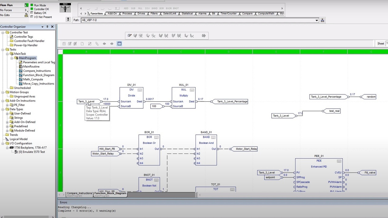
Okay. Let's look at a couple simple examples of function, block logic. So I am here in Studio 5000, which is what we're going to be looking at function block diagram in Studio 5000 specifically. So you can see I've got several instructions here. We're just going to go through some of these, and we're going to start just with a couple very simple examples.
So first let's look at some math calculations and this is where I think function block diagram (FBD) is really good and really useful because one of the things you can do is you can string together your instructions in a sequential fashion, and you can see the way the value, the process value changes at each step through the calculations. So we've just got two connected here together.
We've got a divide instruction and we've got a multiply instruction. So I'm going to take this online so we can see this running and try not to get too distracted with the rest of the stuff, or just focusing on that divide and multiply for now.
So I've got an emulator controller running here and let's see here, so you can see the emulator controllers running there and slot 0. And we're going to take this guy and download
Okay. So the download is completed. So going to go to run mode, and I'm going to ignore that. We'll go to run mode, change controller to run mode or remote run. Yes, these green bars are shown or when the, the row number eight and the column letter R green, then you know, running.
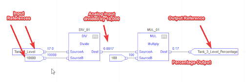
So right here, we have coming into our divide instruction. We have, Tank 3_Level is connected to source A and the number 10,000 is connected to source B.
So Tank_3_Level would likely be connected to an analog input. If we were running this on a real system, it would be reading the level of a tank that was connected to an analog input, say a 4 to 20 mA input module. And we are pretending for this example that the level comes in in terms of gallons. So it's a 10,000 gallon tank that we're measuring.
And so this, this level is already scaled, which could be scaled with your analog input module, uh, with a ControlLogix system. And it's coming in in gallons. Now you could it to percentage like we're going to do here in a minute with the analog input module, but maybe you don't want to do that. Maybe you want to have it in gallons and percentage for some reason.
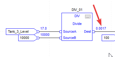
So, what we've got is Tank_3_Level is going into source A of this divide instruction. And the number 10,000 is going into source B. So what happens with the divide instruction, if you're not familiar with this and just take source A divides it by whatever is in source B. So in this case, looks like Tank_3_Level is 17 so 17 divided by 10,000 is going to be put into the destination, uh, which is 0.0017.
So we don't even have to put a tag here, which is another nice thing about function block diagram (FBD). You can just connect it to another source or you don't even have to connect it. You can just see what the output is going to be. So in this case, we're taking a 0.0017, connecting it to source a or the destination of the divide, connecting it to the source, a at the multiply.
And then in the source B of the multiply, we've got the number 100. So we're dividing, whatever's in source eight, divided by a hundred. Uh, we're not dividing, I'm sorry.
We're multiplying by a hundreds to give us a percentage. So let's pull up the watch window here, cover up some of this, and I'm going to just do a quick watch so we can look at only the tags we care about right now, tank three level and tank three percentage or a level percentage.
So take this 17 and we'll just make this a thousand cause that's easily calculated. So get a thousand divided by 10,000 is going to be 10%, right? So a thousand divided by a thousand or 10,000 gives us 0.1 0.1 in here. Times 100 gives us 10. So 10%.
So let's try 5000 that should give us 50%. 5000 out of 10,000 is 50%. So 5000 divided by 10,000 gives us 0.5. And then 0.5 times 100 gives us 50. So that is a quick example. Now, just to show you how this is set up.
If you were to set this up from scratch, I'm going to edit, make some online edits here. You would need an input reference. So that's what these are. So you'd need to input references for your first instruction and 1 input reference for your second for your going to mimic this exact calculation and then we'll need, this is in favorites, but you can also find it in the compute and math tab. We've got a multiply and a divide.
So I'm going to drag that over here. Things are running a little bit slow today. I'm just going to go offline cause it doesn't seem to want to cooperate. Okay. Maybe I was trying to drag it too high.
Again, you would just connect it to 1 of your input references to source B 1 of your input references to source A and then your output of the divide instruction can just connect to source a C just click and drag it. And then when it turns green, you drop it.
And then again with your input reference, you click here and drag it. When it turns green, we drop it and then the destination, we don't have to put an output tag, which is nice.
But if you want to, have an actual tag associated with this calculation, then you drag this, drop it there. Okay. So that's basically how it works.
And then you just add your tags, which I'll show you real quick, just add tags, just like you would with ladder logic, constructions, you can browse form or just type them in there. And then you can just enter your constant numbers there as well. All right. So that is our introduction example.
---
So, we're going to look at 1 more example now, and this is using Boolean logic. So this is, depending on how you look at it. I think it's a little bit worse, not as user-friendly to do Boolean logic in Function Block Diagram versus Ladder Logic.
If you're familiar with gate logic or using logic Gates for Boolean logic, then it is actually pretty intuitive. But I think Ladder Logic is still more intuitive for simple boolean logic, personally.
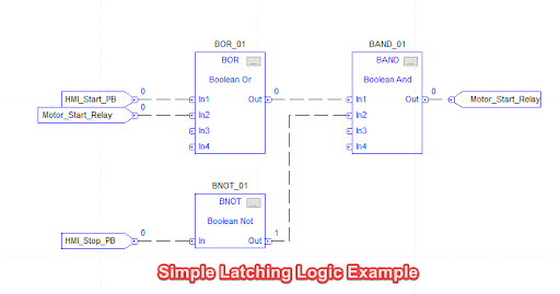
So let's just look at this example here. So we've got a Boolean or a Boolean, not a Boolean. And so the way this works is you can, you've got four inputs for your, or you can connect up to four inputs and if any, 1 of them is true, then the output is going to be true. Or one, if HMI start push button is true, or if motor start relay is true, then it's going to output a 1 here. Okay.
And then with our Boolean NOT, that's pretty simple. You just have 1 input and it's going to flip it from a 0 to a 1 or, or a 1 to a 0. And then the output of the BNOT and the buoy, and, or go to a Boolean AND.
And from there, you and them together, which means they both must be true for the output of the buoy and, and to be true or else it's going to be false. So if 1 of them is false, the output's going to be false. So this is mimicking a basic, motor start latching circuit, or a make-seal-break circuit as I like to call it, sometimes it's just the seal-in logic. So let's run it and we'll just show you how it works here, download
Okay. So that download completed. So now we are going to send our finalize all edits in this program because I started some edits earlier. Okay. And then when we get the green bars, we know we're good.
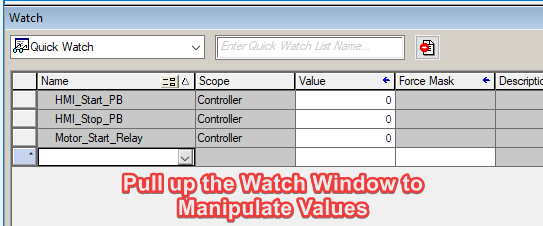
We'll pull up our watch window and I'm going to get rid of these guys and just add our HMI, start PB and our HMI stop PB so we can, manipulate those values.
So what we expect to happen is that when we push the start button, it's going to latch in the start relay. And then once they'll start relay, as on, it's going to latch this in and stay on. Even when the start push button is released. So let's try it out here. So we'll turn this guy to a 1 which makes HMI start PB. 1 makes the output 1 makes this 1, which then makes this a 1. So then when we release the push button, it'll go back to 0.
So now HMI start, PB is 0 motor start relay is one, still produces an output of 1 and a 1 on the motor start relay, the HMI stop. PB is 0 right now. So the stop push button is not pressed on the HMI, which has given us a 1 here and allowing this to be true because this must be a 1. So now if we make HMI start PB 1, or we press it momentarily, that should unlatch the circuit.
So we'll make this a 1 and see, this is 1, this is now 0, which would make this, even if this was still 1, it would make this output false, which is going to unlatch this. And then when we released the stop push button, it should remain off. So this goes back to one, after we released the push button, cause this is 0 now, but these are already 0.
So the output and the start relay is 0. So that's an example of a simple, latching circuit for a motor start type circuit. And again, in some ways it's a little more clunky and a little harder to understand what's going on just by viewing it., then ladder logic, ladder logic is, much more visual for this type of logic because these are just blocks.
And so you have to look at the name of the block to understand what's going on inside. Whereas with ladder logic, it's very visual. You can see what it's doing without much effort.
So that wraps up this intro to function, block diagram.
If you want more to help you become a confident PLC programmer, then check out our PLC training membership called myPLCtraining Academy.
We have PLC and HMI courses, along with support for myself and my team, a community of other electricians, technicians and engineers who are becoming confident, PLC programmers and access to Studio 5000 software and more.
So that's it for now. Thanks for watching. We'll see you in the next video.
Get the Free PLC Cheat Sheet
PLCs are really not that complicated. If you are new to PLCs or just looking to get a better handle on how they work, check out this free cheat sheet, called the "Motivated Electrician's Guide to Understanding ANY PLC System."


New to PLCs?
You can breeze through this cheat sheet in about 10 minutes and get a solid understanding of the big picture of how PLCs work. Perfect place to start.
Recent Posts