Connected Components Workbench - Using the PLC Simulator
In this article we get into how to use the built in PLC simulator/emulator inside Connected Components Workbench (CCW).
Let's get into it!
The CCW software is free at least the standard version is. And it's becoming more and more popular in Industry around the world for a few different reasons.
For one thing the controllers that you can program with this software are very inexpensive. The controllers are the Micro800 series controllers from Rockwell Automation Allen Bradley. And I believe they are all available for less than $1,000.

Many of the controllers come with built-in IO which is another cool feature that saves money and configuration work. so4 smaller automation projects the CCW software and the associated Micro 800 controllers are often a great fit.
Another cool thing about this software is that it can also be used to program HMIs and drives that would be used in conjunction with the Micro800 controllers
One thing that is disappointing about the software is it looks quite a bit different from the rslogix software whether it's Studio 5000 or RSLogix 500 or Micro, all of those software packages have a similar look and feel in the ladder logic.
but the default look of the ladder logic in CCW is quite a bit different. and interface in general just looks totally different
But there is an option to use the Logix theme So that is a nice feature.

But regardless this is a great free software package that you can use to not only learn to program plc's on your own time but also to program inexpensive controllers for practice at home or even to control machines and equipment in a plant. The Micro800 controllers are really nice in a lot of ways and can be used alongside or instead of some of the more powerful PLC controllers.
Now let's dive into the walk-through video of the Connected Components Workbench
Watch the video now
(By the way, if you like videos like this, be sure to check out our membership called myPLCtraining Academy that is full of tutorial and theory style videos to help you become a confident PLC programmer)
CCW - How to Use the Simulator
Prefer to Read it? Go Ahead…
Hey guys, Stephen Gates here from my PLC, training.com with another video to help you become a confident PLC programmer. And this week's lesson and video, which we'll continue this theme throughout the month of April, is about connected components workbench and this is a Rockwell automation product and it's a PLC programming package software that is actually free. The standard version is free. And so I thought this would be really useful to a lot of my audience and who are trying to learn PLCs on their own and need some help. I'm working on it on their own time without having to buy expensive software. So I've covered connected components, work bench in another video and introduction to it, how to set up a new project and so on. So I'm going to skip some of that in this video. If you want to learn more about setting up a new project in CCW as we'll call it from now on, there is a link in the description below that will take you to that video.
So check that out if you haven't seen it already. So in this video we are going to explore the built in simulation options that are in CCW that lets you emulate a controller right from within the programming software. So here we are inside CCW right now.
And again, if you're new to CCW, I'd recommend you check out that previous video I made in the description below because it talks about setting up a new project. So we're going to start out with an existing project here in this video and add some simple logic and then we'll see how it works. Using the, the simulator.
So the first thing I'm going to do here is open program one. So this is our logic routine. So it's open here already.
![]()
And the first thing I'm going to do here is add two rungs. Okay. So we have a total of three rungs. Now I prefer to use the Logix theme, which doesn't do much except change the names of the instructions to look more like RS logic software. So you can see the theme here. You have default, which gives you the instructions. They look a little different. Direct coil, reverse coil output latch. They work the same and they do the same things pretty much. We'll look at timers. I think the timers are a little bit different in both cases. But what I like about Logix is it's what I'm used to, can see the coil. It's like an output, energize output de-energize which does not exist in RSLogix. But you get the idea and then latch bits, output, latch, output, unlatch, and the examine if closed. Examine if open . So we're going to use the Logix theme. That's what I prefer.

So we will add an XIO and a timer to this first room. So let's scroll over till we find timers/counters and we're going to use TON. So again, if you're using the default theme, it may be called something else. Let's just see what that is out of curiosity. Okay, so it looks like it's called the same thing. So that's good. Stick with Logix here. Okay, so we're going to add a ton there. And then on this next rung, we are going to add a XIC and an OTE. Now before we address anything, let's just talk about what we're going to do with this. So we're going to monitor, this'll be an input and we're going to add a delay onto it with the timer. So if this input drops out, so to speak, the contact closes, because it's an, it's a basically a normally closed contact.
So when de-energize the contact closes timer will start, it's gonna trigger this normally open contact, which will then trigger our coil and turn on an output. So the input dropping out starts the timer, which then turns on the input after the preset time is reached. Okay, so we'll build it out from here. So for this first rung, we need to add a variable here to this instruction. And a variable is just a tag. That's just what they call it here in CCW is tag. So let's, okay, so they, they can remember here, I think if I double click the actual instruction, there we go. As you can see, I'm not as comfortable with CCW as with the RSLogix and Studio 5000 software. But if you poke around, it's not too difficult to figure out. So the variable selector is coming up here.
And what we want is I/O because we are going to be using the inputs and outputs from the micro eight 50 controller. And so I actually have already set up an alias for one of these outputs. So this is discrete output DO:00 so that's our output. Let's find our inputs. Okay, here's where discrete input: DI:00 is. So this is the guy I want. So we're going to say basically when this becomes true, so when the input turns off, there's an active alarm. Okay?

So then with the timer, it's already given us a timer variable there. So what we need to do is to set up a preset time. So to do that you can add a variable there or ah, let's see, I can do this. There we go. So then you can actually just type a time in there. So if you type T#2, seconds for our example here so S, that will get the timer to start timing and then it will take two seconds to complete the timing. Okay, so that rung is done.

Now our next rung we want to turn on when this timer output completes. So we could have actually just skipped this second rung and just put this OTE here. But if you're familiar with RSLogix and Studio 5000 software, a timer needs to be the last thing on your rung. And C, you would use the done bit of the timer to activate something on another room. So we're, we're kind of trying to emulate that here.
Okay. So next we need to address this instruction, which like I said is going to be like the Done Bit from this timer. So we'll use this cubit cause there is no done bit, but the cubit in CCW works the same as the done bit in RSLogix software. So double click and we'll go to global variables and we're going to search for time, see if that gives us anything.
TON Nope. Let's see if we can find them here. Maybe system variables. So there it is in the local variables. It's TON one. So this is the guy we want. And then we have to put dot Q to address that done bit or the cubit. Okay. So now on our output, we will address this OTE to one of our physical outputs. On the controller. So again, I've aliased alarm light two discreet output 00. So we'll double click that. Okay. And there's our logic, simple as that. So now we're ready to build the project and make sure there's no errors. So that's this button up here and I like to click on this error list and make sure there's nothing there. You can click on the output as well. Build started. Looks like it may be still working on the build her list.

Okay, so the build project is completed. There are zero errors, zero warnings, zero errors, zero warnings, that's a good thing. And hear my son laughing in the background, which is always a great thing.
And it's still working. It takes, it takes a few minutes to build the project. So what we're going to do after that's done is we're going to bring up the simulator and we're going to start walking through that process, which is what you really will get out of this video. Build succeeded. That's what I wanted to see. One succeeded, zero failed. Okay. And these notifications are very, very annoying. Okay. So the next step is to darter simulator. So there's really four steps to getting your project in the simulator and testing it out.
So those steps are to make sure your controller for the project is a Micro850 SIM, and that is this number here, Micro850 SIM, and there's a specific catalog ID for that controller. So if you don't have that set up as your controller what you can do, obviously, if you're not sure, just click properties here, but what you can do is change controller here and this'll bring up the controller that you're using and the controller that you want to change it to. So current, and then you can change it to whatever. There's a whole list of controller options here. So if yours is not already this controller, you'll see that as an option in this list, assuming that you have version 12 of CCW. That's an important distinction. Not all the versions of CCW have the simulator that I know of. So just be aware of that. And so it's, you know, hopefully bring up the about window there.
Okay. So this finally came up from the help and about button there. And we can see that I've got version 12.0 0.0 standard edition. So just make sure that you have at least version 12. And that way you'll, you'll have to the simulator. Okay, so the four steps to run a project on the simulator are number one, make sure your controller is the Micro850 Sim, like I said, number two, start the Micro800 simulator of, show you that in a second. Number three, sync your module configuration with the simulator. And number four, download a project to the simulator. Like you would a regular controller. Okay, so we've figured out step one, make sure we've got the 850SIM controller set up. So step two is to start the Micro800 simulator, which can be done with this button here. So click that button and it's going to bring up a separate window that looks like very similar to this Micro 800 controller picture and with the fuse few controls. So failed to launch simulator application. There we go. So it took a minute, but it did come up. Okay.
So once that is up, the next step is to make sure this is kind of still part of step two or we start the simulator. Just make sure your Ethernet card is selected here. Don't choose the software loopback interface. This will allow you to use the Ethernet driver in your RSLinx to, to connect to this controller.
Okay, so after we've selected the IP address, the third step is to synchronize the module configuration. So there's this button here, you should see these four buttons up here and just click the furthest one on the right. Synchronize the module configuration module configuration in Micro800 simulator will be replaced. Continue. Yes.

So once that is synchronized, let's make sure that it is synchronized. So you can click it more than once, but you should only need to do it once. Okay, number four, it's time to download our project to the simulator. So power up the simulator rack by clicking the power button here. That's also one here. So we'll just click that button. There it goes, it's running. So now we can click right click in our controller here in the project and download. So if we go here, right click the Micro850 select download,
It's going to bring up a communication window, very similar to RSLinx, classic or RSWho if you've used RSLogix or Studio 5000 software . Okay. And then this next dialog box will pop up. This is the download com confirmation marks and we'll just click download. Then after complete downloading, it will give us a one more request to see if we want to put it back and run mode. So we'll wait for the download to happen. Whenever I'm recording video, these things take a little bit longer. So hopefully your it will go a little bit faster for you. But my computer's trying to share resources as I record video and do these software operations
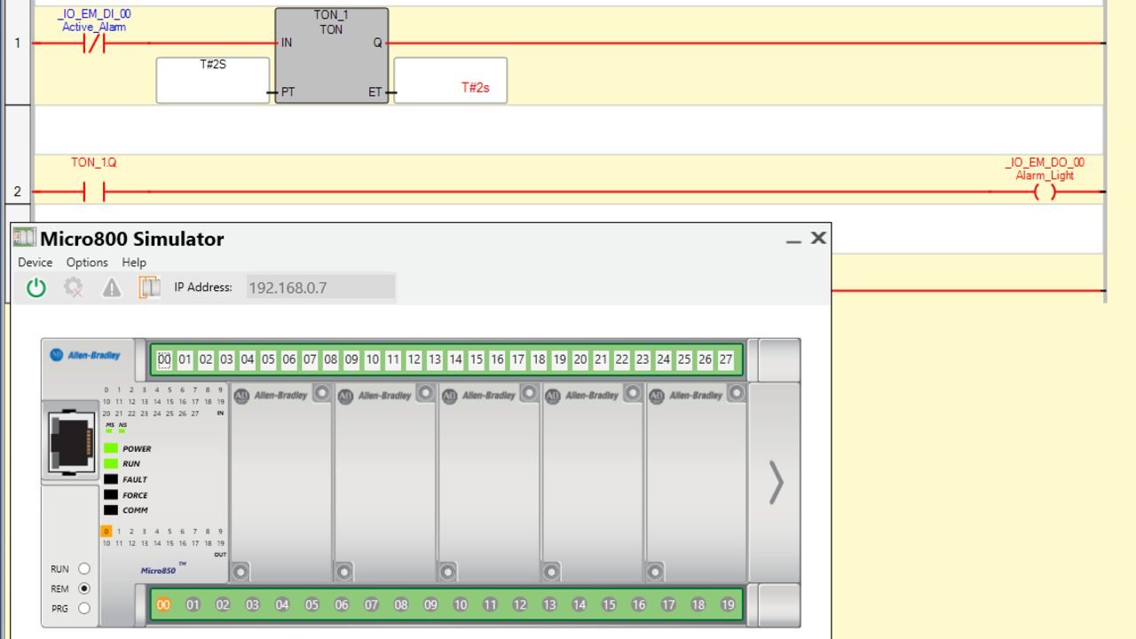
Okay. So then like I said, we get this box that comes up and says download is complete, change the controller to run mode to execute controller project. Yes. And then we get one more box that has a warning that says it can only operate in run mode for 10 minutes at a time. And then after that it's going to be switched to program mode automatically. So that doesn't mean you can only simulate for 10 minutes. It just means after 10 minutes you'll have to re put it in run mode. So it's kind of annoying. But that's their way of limiting their soft, their free software. So just click okay. And now our program is running in the simulator. So you can see it's in run mode here. And you can see these all represent the LEDs for the different inputs and these represent the LEDs for the outputs. So you can see output 00 is on. And if we look at our logic again, that will make sense here.

Okay, so here is our logic again and you can see that it's all red, meaning that it's active. So discrete input, 00 is off. So that makes this true. And the timer has already hit two seconds. So that makes this true, which is red. And that makes this bit true, which makes the rest of this rung true, which turns on the output. So let's see what happens when we turn on input 00. You can see it immediately turned off output 00 and the ladder logic reflects that. So then if we want to toggle it back off, we should see after two seconds this output will come back on and sure enough the output came back on.

All right, there you have it. Now you should be able to simulate your own projects with CCW using the simulator. Hope you found this video helpful. If you're serious about becoming a confident PLC programmer, then I'd recommend you check out my PLC training Academy, which is our membership for electricians, technicians, engineers, or students who went to improve their skills and career options by adding automation skills to their tool belt.
And one thing I did want to note is that we don't actually have any CCW courses in the membership at this time. But we will be adding some later this year in 2020. But we do have extensive training on other Rockwell software and it will all be applicable to CCW or most of it will be applicable anyway. And there's a lot in there that can, can help you become a confident PLC programmer. So check it out. So check out the membership, myPLCtraining Academy here. Thank you for watching and we'll see you in the next video.
Want more free stuff on CCW? Check out the resource bundle we put together. This is a curated list of other free Connected Components Workbench software tutorials.
Get the Free PLC Cheat Sheet
PLCs are really not that complicated. If you are new to PLCs or just looking to get a better handle on how they work, check out this free cheat sheet, called the "Motivated Electrician's Guide to Understanding ANY PLC System."


New to PLCs?
You can breeze through this cheat sheet in about 10 minutes and get a solid understanding of the big picture of how PLCs work. Perfect place to start.
Recent Posts