Discrete Vs. Analog I/O
This month’s topic is Discrete I/O vs Analog I/O.
If you’ve delved into PLCs at all, you should know what PLC inputs/outputs (I/O) are. But here’s a quick refresher...
PLC I/O is the part of the PLC that connects the brain of the PLC (the CPU), to the outside world, the machines, the switches, the push-buttons, etc. In a PLC system there will usually be dedicated modules for inputs and dedicated modules for outputs.
An input module detects the status of input signals such as push-buttons, switches, temperature sensors, etc.. An output module controls (turns on/off, ramps up/down, etc.) devices such as relays, motor starters, lights, gauges, etc.
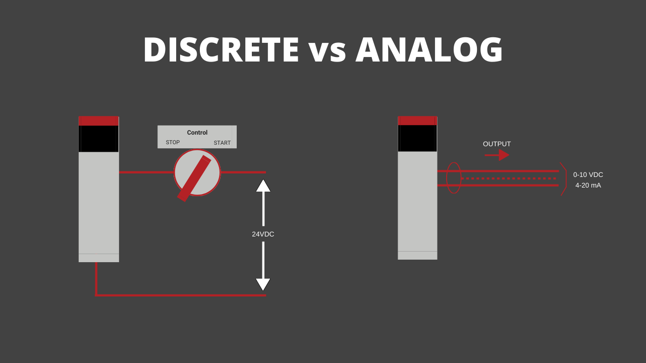
Discrete/digital I/O is either on or off (think light switch on or off). Analog I/O can be on or off or in between (think light switch dimmer).
The inputs tell the PLC what to do with the outputs (depending on how you've programmed the logic).
We are all familiar with computer I/O (you're using it right now). For instance the keyboard you type on is kind of like a big discrete input module to the computer with a bunch of separate input channels, where each key is an input channel.
Your monitor screen is like a big analog output that pumps out various images and screens depending on a combination of input from your keystrokes (and mouse clicks) and the built-in programming of the computer.
Ok, that’s the quick intro to discrete vs analog I/O for PLCs. But we are going to dig in even more...
Let's quickly consider what discrete vs analog I/O in a plant or factory environment, discrete inputs would be things like push-buttons and relay contacts, discrete outputs would be things like motor start relays or alarm lights, analog inputs would be things like tank level sensors and analog outputs would be things like control valves.
Ok, so with that in mind let’s jump into this quick video I made for you explaining how to add and use I/O in Studio 5000.
DISCRETE VS. ANALOG I/O
Prefer to read it? Go Ahead…
Hey guys, Stephen Gates here from my PLC training.com and I've got another video for you today to help you become a confident PLC programmer and automation pro. This video is about analog and discrete I/O and, specifically I/O modules and how to use them in Studio 5000 Logix designer.
So we're not going to go into great detail about how discrete and analog I/O work in this video, but I just want to give you a quick summary here before we get started. So discrete or digital is another name for it. I/O is either on or off. So think of a light switch where the light is either on or off or off or on, whichever. And then analog I/O would be more like a dimmer switch where you can adjust the brightness of the lights up and down.
----------------------------------------------------------------
Get the Free BONUS Lesson
----------------------------------------------------------------
So all the way up it's fully bright and then you slowly dim it until it's off. Cause that would be something comparable to analog IO. So just to clarify, when I say I/O, I'm talking about inputs and outputs.
I for input O for output. So the discrete and analog inputs will be devices that are external to the PLC and they're wired into the PLC to tell it status or position of a machine or take a control selection from an operator. Like when they push a button or turn a switch, tells the PLC what's going on and outputs whether it's discrete or analog there. Those are the devices and or machines that are being controlled by the PLC.
So, in a plant or factory environment, the discrete inputs would be things like push buttons like we said earlier, relay contacts that are connected to the PLC and discrete outputs would be things like motor starter relays where the, the PLC is telling the motor to start alarm lights or other things that are on or off. And those again are being controlled by the PLC.
Analog inputs would be things like tank level sensor, so how full the tank is, um, that are connected to the PLC. And analog outputs would be things like control valves or variable frequency drives controlled by the PLC.
So control valves would be a valve where the PLC can open it a certain amount, open it all the way, close it all the way open at 50% so on variable frequency drives would be something where you're adjusting the speed of a motor through a drive. Okay, so that's a quick summary of analog and discrete digital IO, the differences. So we're going to get into the software now.
So here we are in Studio 5000 Logix designer and I've got a project created already with a CompactLogix 5069-L310ER controller. Okay, so the first thing we're going to do is we're just going to add four I/O modules to our project here.
So we go to the I/O configuration here in the controller organizer, we find the back plane, right click, click new module. And first we're going to add a discrete input module and there we go. And so we can use this filter section to help us find what we want.
So I'm going to un-check that and then click digital. So again, digital and discrete I/O is the same thing. Now we have some options here. As you can see there's several modules. We're going to choose an input module to start with.
So uh, I'm just going to choose the first one available here. So the part number for an input module almost always have an eye in it. So this is a 16-point 79-264 volt AC input. So I'm just going to double click that and no need to give it a name. When this new module properties comes up, we can just hit okay. Okay.
Next we want to add a discrete output module. So we will leave the filter set on digital because this is a discrete or digital output and we're going to look for modules with the letter O in the part number or the catalog number. So we have several here. Let's say we want an output module that uses AC voltage as well. So our input volt or input module uses AC voltage.
Let's get an output module that does as well. We'll go for the OA16 double-click, no need to name it, just hit okay. Okay. Next we're going to add an analog module. So we'll do an analog input module to start with.
As you can see, there's not as many analog I/O options just because there's not as many, uh, as much demand for different types of analog I/O. So we will choose this first one, which is an eight channel voltage or current in a log input module. So double click hit. Okay. And lastly, we are going to choose an analog output module.
Click the OF4 is a four channel analog output module. Click okay. And then we're going to close this. Okay, now our I/O configuration should look like this. We've got our controller and slot zero, the discrete input module in slot 1, the OA16 in slot 2, the IF8 in slot 3 and the OF4 in slot 4.

So now let's see how we can use these I/O points in our logic. So we're going to go to the main program. So this is the default program in a new project when you create a project in Logix designer. So open the main program and open the main routine. And I'm going to delete that cause we're going to create it from scratch.
So for the sake of time we're going to be adding the simplest logic possible. So on rung zero we are going to add an XIC, this guy here and an OTE. So, for the XIC we want to address this to our discrete input module or digital input module. So if you double click this question Mark and then click the pull down menu.
Here you can see what addresses are available from our I/O modules. So our discrete input module is the over here, which is in slot 1 again. So if we go to Local:1:I - for slot one I for input, expand that.
And there's different options here but we want to find something specific. So just a quick note that the syntax for addresses I/O modules varies from module to module. So you may need to look in the manual for a particular module if you're unsure of how to address it's points.
So just do a Google search for whichever module that you're working with. So usually the catalog number is a good place to start. So in this case it would just be 5069-IA16.
You could put Allen-Bradley too if you like, but generally the instruction manual or user manual or something should come up and you should be able to find out what the proper syntax is for addressing it, but a lot of times you can just figure it out by scrolling through and seeing what's available.
So like I said before, if it's an input module, it's going to have an I somewhere in it and that number corresponds to the slot number of the module in the rack. So I happened to know the syntax. And the proper syntax for this module is Local:1:I.Pt00
So there's 16 points. And so this is our zeroth point. So if we just expand that guy, then we have some more options. We want the data option. Okay. So almost always you're going to be referencing the data member of a tag for, for whichever I/O point you're addressing to. Okay, finally we got it. All right.

So then that's coming from our input module. And this is going to drive an output. So in the output case, our discrete output module is slot 2. So pull this down Local:2: - and we want, O, this time for output.
And we're going to use Pt00 on this. But, we could use Pt01 or Pt02, or whatever, but we're going to use point zero, expand that in again, it'll be data. So you see the, the format looks really similar for these. This one just has a 1 and an I and this one has a 2 and an O, okay. So that looks good.

Let's add a second rung here. And on this rung we will put an LES instruction, and this is a less than instruction. So you use this when you want to compare, compare a value to another value and see can take a tag and compare it to a fixed value. Or you can compare one tag to another tag. And just a quick note, uh, the logic I'm created is not recommended for anything in real life. This is just an example to show you how to address I/O modules directly in your logic.
So we'll put our less than instruction there. And then on the right we are going to put an ADD instruction. Come on. There we go. So in our LES instruction or "less than", we're going to put the address of one of our analog input points or channels, our analog input modules and slot three. So if we pull this down, scroll down to local three, expand that. And this one's going to look a little different. So instead of Pt00, it's going to be Ch00, so similar.
Then we'll expand that Ch00 and we're looking for .Data - very good. So it's similar to that one, except instead of Pt, we've got Ch for channel. And let's say we're comparing this to the number 10 for the sake of this example. And next we're going to control and vary an analog output based on this LES instruction.

So if we go over to our add instruction, we're going to use channel three. So we're going to use the destination of the add instruction. And again, I'm not going to get into the details of how to use an add instruction. That's for another video and other time, but the destination is what we're focused on.
That's what's going to control the output in this case. So slot four is our analog output module, the 4 - then expand the 4:0. And in this case, instead of just using channel zero, we're gonna use channel 3 just to do something different. So expand that and then scroll down to Ch03.Data.

And for the ADD instruction, we will say that we're going to add 5 to the input. So I'm going to take this guy, copy it, put it here in the source a. And so we're saying if the analog input is less than 10 we're going to add five to it and put it into the analog output.

Again, this is not recommended for anything, it's just a demonstration of how to you, how to use your I/O modules and how to address it appropriately. Okay, so that wraps up this video. Hope you found it helpful and hopefully you have a good idea of how to use analog. And discrete I/O modules in Studio 5000 Logix Designer and how to address those points in your latter logic.
Obviously there's probably a lot of gaps for you if you are new to PLCs. This may have brought up more questions than answers, and if that's the case in you're looking for more help with learning PLCs and becoming a competent PLC programmer, check out myPLCtraining Academy. That's the membership that we've created for automation training to help electricians, technicians, and engineers become confident PLC programmers. So hope this video is helpful. If you need more help, check out the Academy and I'll see you in the next video.
-------------------------------------------------------------------------
Want more free tips on this topic? I created free PDF bonus lesson on how to scale analog I/O using the module configuration settings in Logix Designer. Just click the button below and enter your info so I can send you the bonus lesson.
Get the Free BONUS Lesson
Get the Free PLC Cheat Sheet
PLCs are really not that complicated. If you are new to PLCs or just looking to get a better handle on how they work, check out this free cheat sheet, called the "Motivated Electrician's Guide to Understanding ANY PLC System."


New to PLCs?
You can breeze through this cheat sheet in about 10 minutes and get a solid understanding of the big picture of how PLCs work. Perfect place to start.
Recent Posts