Learn FactoryTalk View HMI Design

I have been getting a lot more requests from people who not only want to learn PLCs but also need to learn how to set up HMIs to talk to PLCs.
PLC logic programming is really just one piece of a bigger puzzle. It's a very important one but you need to learn some other skills along with it if it's going to prove useful in your career.
In this article we will be covering HMI programming and design. Particularly HMI programming and design with FactoryTalk View software.
Since we focus our training on Allen-Bradley/Rockwell automation products, FactoryTalk View is the HMI software that we know and teach our students.
FactoryTalk View is very powerful, but also pretty easy to use if you’re just getting started.
If you want more resources to learn FactoryTalk View after you read this article check out the link below to get a free PDF I create for you.
But let’s back up a minute and clarify what an HMI is…
What is an HMI?
HMI stands for Human-Machine Interface. Also, sometimes OIT (Which stands for Operator-Interface Terminal) is used instead of HMI.
And sometimes the term SCADA (Supervisory Control and Data Acquisition) is even used instead of HMI. But technically SCADA is more than just and HMI.
But basically and HMI is a computer screen of some sort that has software on it that lets you see what’s going on and/or control what’s going on with a machine or group of machines. And usually it’s monitoring and control capabilities are going through a PLC that’s already controlling and monitoring the equipment.
Essentially, the HMI is a more user-friendly way to monitor and control the PLC and the automated equipment.
So, for example, let’s say we have a super simple HMI screen that is set up to allow the operator to start and stop a pump (call it Pump 1). Additionally they can tell whether the pump is already running or not.
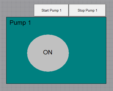
So the HMI is then configured with a couple buttons that will connect to tags/bit addresses in the PLC controller that are logically programmed turn on/off the output to start/stop Pump 1.
Similarly, the HMI has animation graphics that are connected to the PLC tag(s) that indicate when the pump is running or not.
Ok, so that’s about all there is to it, an HMI is a computer with software that communicates with the PLC and allows you to monitor and control tags in a PLC and thus control and monitor the automated plant equipment.
Don’t forget that we will be releasing a new FactoryTalk View HMI course in late 2019. Lock in your myPLCtraining Academy membership now and get access to the HMI course when it releases.
The truth is after you’ve learned to program Allen-Bradley/Rockwell PLCs, designing and configuring basic HMI screens is not only easy but really fun! So I highly recommend you start learning HMI design/programming skills if you already have some basic PLC programming experience.
The best way to get started learning anything software based is to see a demonstration of someone using the software, so that’s what I’ve done for you. Check out this free video I created for you where I walk you through FactoryTalk View Studio.
FactoryTalk View Video Walk-Through
Prefer to read it? Go Ahead…
Hey guys, it’s Stephen from myPLCtraining.com, and I’ve got another video today to help you become a confident PLC programmer.
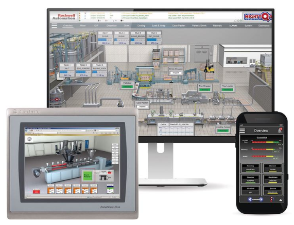
This video is on FactoryTalk View SE which is an awesome HMI building software from Rockwell Automation that works beautifully with Rockwell PLCs and PACs.
Let’s open it up and create a project so you can see what it looks like.
So when it first opens up you can choose between 3 different types of Site Edition Applications or a Machine Edition application.

Machine Edition is typically used for PanelView Plus projects but in this case we want to create a basic SE application to run on this PC so we will choose “Site Edition Local Station”
Now we are able to open an existing application here or choose to create a new one. Let’s create a new project now. And we will call it Confident_HMI_Designer

So, now it needs to load and open the new application.
Ok, so before we dig in too much let’s take a quick tour of what you’ll use most in the software.
Graphics/Displays
First, let’s look at graphics. Here’s where you’ll set up your displays which is where 95% of your time will be spent developing an HMI application. We’ll actually set one up here in a little bit so stand by for that.
FactoryTalk Linx
Ok the other key ingredient to getting started with setting up an HMI application is configuring the communications to the PLC.
So to do that, we need to find the application name at the top and right-click on it. Now select “add new server” and find Rockwell Automation Device Server (FactoryTalk Linx). This is basically the RSLinx equivalent for HMI software. In fact they use to call it RSLinx Enterprise.
Ok now that that is added, let’s open it up and configure our comms to the PLC. So here it is, but next time you open the project it would probably be down here. Don’t ask why, just remember to look down around for it after you create it and then after you reopen the project.
So expand it and double-click the “communication setup”
You should see this screen now that looks like the RSWho window in RSLinx Classic. By default you have two drivers show. The 1789-A17 virtual backplane and the ethernet driver.
So, if you right-click the RSLinx Enterprise icon, you can actually add other drivers too such as DF1, ControlNet, Remote I/O etc.
But for now we are just going to communicate with our emulator through the virtual backplane driver. So expand that and notice I already have a emulator controller showing up here.
And that’s because I have the emulator running over here with a controller added in slot 0.
Now, to make our HMI application to point to that controller, we need to set up a device shortcut, so over here click add and then give it a name. Anything is fine, we’ll call it FTView_Controller. And then we need to select the controller that we want to associate with this shortcut and click apply.

Now you could add more device shortcuts to other controllers if you wanted but that’s all we need for now.
So now we just click “verify” and check that it looks good. Then just click Ok and we are done with the communication setup. Pretty simple right?
Design a display
Alright now for the fun part. Let’s create a simple display to monitor and control tags in our PLC.
So, we are going to create a super simple display that allows to monitor the running status of a pump and also allows us to control the pump by starting and stopping the pump.
Ok, so first let's create a new display.

Next let’s just place our basic shapes and push-buttons on the display.
Ok, now we need to take a minute to look at our PLC logic that we are connecting to this HMI application. The logic for this PLC allows us to turn on and off the start_pump_1 relay which runs the pump motor.
So as you can see we have set up the logic with tags called HMI_Start_Pump1 and HMI_Stop_Pump1 and simple latching logic that works the same as seal-in ladder circuit but uses the OTL latching and OTU unlatch instructions instead of one OTE.
So when we push the start button on the HMI we want this logic to latch in the start_pump_1 relay and then we are going to add a stop button to the HMI that will unlatch this rung when we want to stop the motor.
Pretty simple right. Ok, one more thing I want to show you in our logic is that I’m simulating the pump running. So when we send the pump a start signal I use other logic to simulate the pump starting by having the other logic latch in the Pump1_Running input tag after a 3 second delay.
So, real quick I’ll show how the logic works before we finish our HMI screen. So I’ll toggle the Start bit and then toggle it back off and the pump is starting and now it’s is running and stays running.

Now I want to shut off the pump so I’ll toggle the stop bit on then off and the start pump relay drops out and the pump1_running input drops out.
Animate/Set Control Tags
Ok, so now we are ready to finish setting up the HMI application so that objects on the display will communicate with our PLC program.
So, the first thing we want to is set up our start pushbutton to drive the correct tag in our PLC program which again is HMI_Start_Pump1. So double click the start button and then go to the connections tab
Ok, now we need to select our tag, so click the ellipses. Now we need to look for the communication shortcut we set up earlier in FactoryTalk Linx. We called it FTView_Controller. So click to expand that and then go to the online folder. Now if it’s not show here then simply right-click the one of the folders that is shown and select “refresh all folders” It should show up at that point.
Now that we selected the online folder for our emulator PLC at the FTView_Controller shortcut let’s find the tag we want which again is called HMI_Start_Pump1.
Then we will go to the up States tab which will be the appearance of the button. So for both State0 and State1 we will type "START".

Ok, now that we have set up this start button, let’s duplicate it and then make the duplicate a stop push button. So right-click and select copy and then right click here select paste or just use the keyboard shortcuts ctrl+c and then ctrl+v to copy and paste.
Then we will move it over here, double-click the button to adjust its properties, so first let’s change the tag to the the HMI stop pushbutton here…
Then we will change the up appearance to say “STOP” then click ok and we are done with that button.
Great. Now let’s add some animation on the pump object. To Start let’s just some simple text that says whether the pump is running. In this case we'll say "Pump 1 Running". So we go over here to create a new text object and just type Pump 1 Running.
Now we need to apply some animation to the text objects. So right-click the ON text and choose animation and then select visibility. So we will show this one when it’s running and hide it when it’s not.
So now we choose a tag from our controller which would be the pump running tag then click ok etc
Apply and close.
Ok now for the fun part. Let’s test it.
So the easiest way to test your display is to just hit the test display button here that looks kinda like a play button.
So now we can see the pump is off. Let’s see what happens when we press the start pump 1 button.
Ok, we pushed it and now we should wait a few second for the pump to start. And there it is. We can see that the pump is now running.
And to stop it we just hit the stop push button and wait a second and there it stopped!
Alright, there you have it! You now know the basics of setting up a simple HMI display and configuring the communications and tag animation on the display to interact with a real PLC.
I hope you’ve enjoyed this introduction to FactoryTalk View Studio.
Here's a couple ways I can help further:
Get our free resource bundle of resources to learn FactoryTalk View
Need PLC/PAC/HMI training for yourself? Join the membership, myPLCtraining Academy.
Need PLC/PAC/HMI training for your COMPANY? Schedule a free call with me to help you make a plan for training your maintenance team.
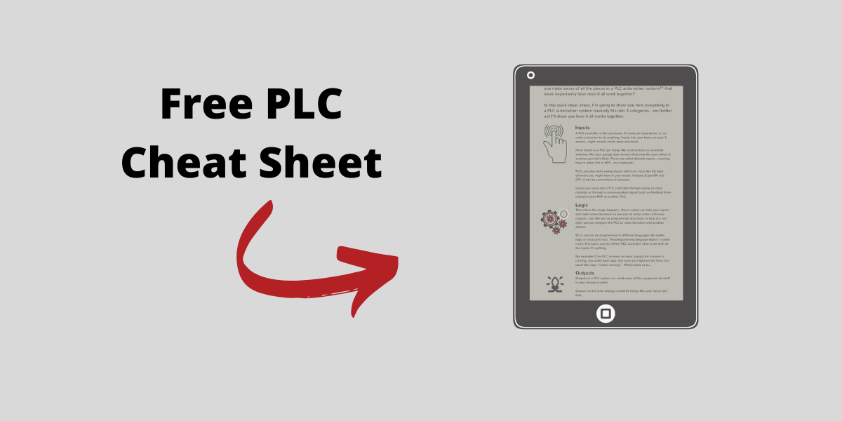
Get the Free PLC Cheat Sheet
PLCs are really not that complicated. If you are new to PLCs or just looking to get a better handle on how they work, check out this free cheat sheet, called the "Motivated Electrician's Guide to Understanding ANY PLC System."


New to PLCs?
You can breeze through this cheat sheet in about 10 minutes and get a solid understanding of the big picture of how PLCs work. Perfect place to start.
Recent Posts