Studio 5000 PLC Software Training
In this post, I’m going to be sharing about Rockwell’s flagship PLC/PAC programming software called Studio 5000 Logix Designer.
This software used to be called RSLogix 5000 and if you’re serious about learning PLCs to advance your skills and career you’ll likely be using this software a lot.
You’re going to need to get really comfortable with this software if you’re going to prove to employers/bosses that you have what it takes to be automation/controls technician. So, I highly recommend that you focus on PLC training that focuses on Studio 5000.
We will be breaking down this software in quite bit in this post, but to start I wanted to do a quick overview of what the software does.
- Logix Designer is where you will create all your programming logic for your PLC automation.
- This software is used to program ControlLogix and CompactLogix controllers and is also used for programming the Studio 5000 Logix Emulate controllers, which are software based controllers you can run on your computer for simulating and testing your logic.
- This software is also where you will set up your input and output module configuration
- Studio 5000 Logix Designer uses tag-based addressing which is different than the older A-B PLC programming software such as RSLogix 500 which uses a data file addressing structure.
- BONUS: You can get free access to Studio 5000 Logix Designer when you join our membership, myPLCtraining Academy (you won’t find this anywhere else)
Ok, that’s your intro to Studio 5000 Logix Designer! Here's what you can expect in the rest of this free PLC training:
- A video walking through Studio 5000 Logix Designer.
- A list of resources (free and paid options) to help you learn more about Studio 5000 Logix Designer.
Click here to get the resources
By the way, if you don’t want to wait around and are ready to dig deep into Studio 5000 Logix Designer so you can improve your career with PLC skills, check out our PLC training membership, myPLCtraining Academy.
So without further ado, here’s the video I made for you to walk you through how to navigate your way around Studio 5000 Logix Designer.
Studio 5000 Logix Designer Walk-Through
Prefer to read? Go ahead...
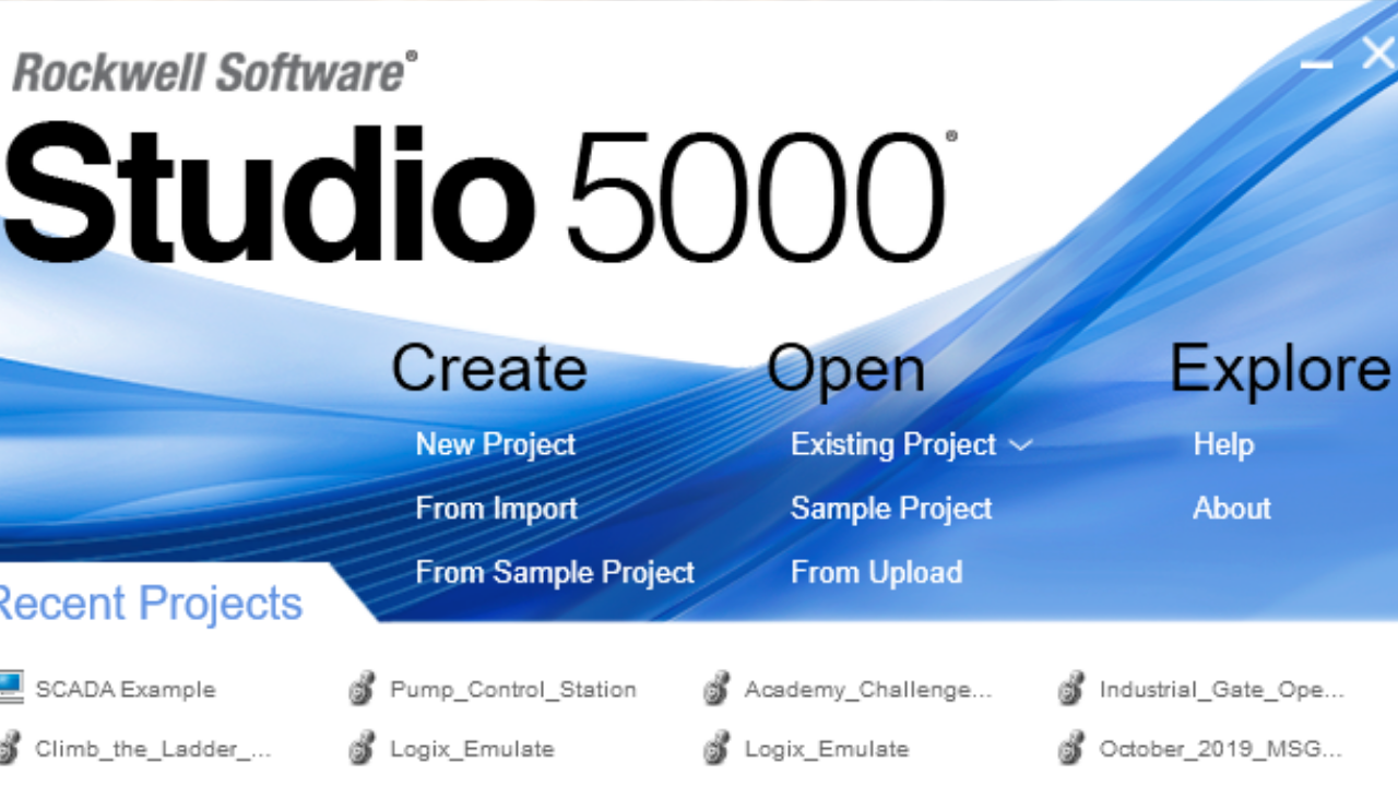
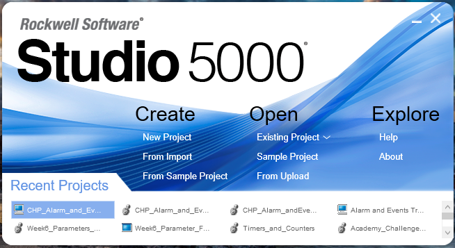
Hey there, it’s Stephen Gates with myPLCtraining and welcome to this walk through video of Studio 5000 Logix Designer. So first of all I want to let you know that I have another video that shows you how to set up a new project. And you can watch that video here if you’re interested.
Ok, so here we are inside an existing project in Logix designer and so let’s look at the Controller Organizer here on the left. We will start from the top.
Controller
First we have the Controller name that was specified when the project was created. And if you double-click the controller name here it will open the properties for the controller that was specified when the project was created.

...and then if you expand it we have the 3 items. The controller tags, controller fault handler and power up handler. The fault handler is where you can place some logic that runs whenever a fault occurs and the power up handler is where you put logic that will run whenever that controller powers up.
Those two items are for more advanced programmers and not required for most simple PLC automation projects.
The controller tags folder is important for all PLC programs though. This is where you can create, edit and monitor tags for your program. And if you don’t know what tags are, they are basically the way you reference the inputs and outputs of your PLC. You can also create tags to be placeholders for internal data like timers and counters and calculated values that you want to use in other parts of the program.

So for example, in this project I have several tags created. I have inputs and outputs. So the Tank_1_Drain and Tank_1_Fill would inputs that are either on or off and the Tank_1_Drain_Relay would be an outputs that I turn and it’s also a BOOLean so it would be either on or off and then we have another tag that stores that value of the level of the tank from 0 to 100%.
So, that’s intro to tags. There’s more to learn about tags but we don’t have time to cover all that here. (Learn about tag aliasing here).
Tasks/Programs/Routines
So let’s move down the line here and look at Tasks. Tasks is where your programming logic will live. There are three levels of for organizing your programming logic. Tasks, programs and routines. So tasks are like folders, programs are the subfolders within the tasks and routines are like files in the subfolders and this where you actually create the logic.
So here you can see I have the MainTask which is included in every program by default and within the MainTask I have the MainProgram and within the MainProgram I have a few routines. I have the MainRoutine and then simulation and Tank_Level_control.
One thing to notice about the MainProgram is that it has a little “1” on it which means it’s been selected as the main routine, but not just because it’s named main routine. If we select the program and then right click select properties and then go to the config tab you can choose which routine is the Main and “MainRoutine” is selected.
And of course within the routines you can see the actual ladder logic that is programmed for the project or you can add and create your own logic in these routines.

And you could also create these routines to be structured text logic or function block diagram (Assuming you have the appropriate license).
Adding new tasks, programs and/or routines is simple...see the screenshot below.

Check out our free PLC training on using comparison instructions in ladder logic.
Data Types
Ok, the next thing I want to discuss is the data types folders. There are several categories here and honestly you don’t need to use these folders very often but I just want to introduce you to a few of the main data types in the “predefined” section because these are the ones that are there by default and that you’ll use a lot.
So when you expand this you can see there are a ton of predefined data types. But let’s start with the simplest data type, the BOOL. The BOOL data type is a boolean value meaning it can only be a 1 or a 0. Now what’s interesting about the rest of these data type is they are basically all some combination of BOOLs.

So if we look at a DINT tag in the controller tags folder and you expand it it’s actually a combination of 32 BOOLs.
And a INT is 16 BOOLs, and every other data type is a combo of BOOLs, INTs, FLOATs, which are all ultimately combinations of BOOLs.
I/O Config Tree
Ok, the last thing we are going to cover in this walk-through is the I/O config tree. This is where you put all your identify all the input and output modules that you will have in your PLC rack chassis that you need to control and monitor.
So, as you can see we have 4 modules in our chassis. The first module is slot 0 is the controller. The controller is often in slot 0, but for ControlLogix and Emulate Logix like we are using here, you do NOT have to have the controller in slot 0. It can be in any slot of the chassis and you can have more than one controller in the rack if you want.
Next, in slot 1, we have a 1756-IB16 module which we can check out by double clicking. As you can see this is a 24VDC input module. There’s different things you can configure with this module but generally these simple modules don’t need much config.
And next we have a 1756-OB16E which is an output module. Again we can double-click and see the details of the modules here.
And lastly, I have a 1756-OF4 here that is an analog output module. This module has some more options since analog modules usually support different configurations such as different voltage ranges or current ranges.
But the point is that this is where you’ll view the configuration and properties of any I/O module in your system. And to add a new module, you just right click the backplane and click “new module” then just search for the module you want to add to your project.
And that’s it for the I/O config tree.
Let’s review what we covered in this walk-through video:
- We walked through the most important items in the controller organizer
- Starting with the Controller area, I showed you how to view the controller properties and then how to view and add controller tags
- Next we looked at the Tasks section which is where your logic will live. Tasks are the biggest container and hold the programs. Then within programs you have routines which is where you put the actual ladder logic or structured text.
- Next we looked at Data types and showed how all computer data specifically PLC data is a combination of 1’s and 0’s or on/off signals. The BOOL data type is what is used for discrete inputs and outputs such as switches push buttons or motor starter coils and INTs, DINTs and REALs are used to display store and drive analog data such as tank level sensors, pressure transducers or motor speed controls.
- And lastly we looked at the I/O configuration tree where all the input and output modules are located and how to view module configuration or even add modules to the project.
That’s all for this video! I hope you helpful. Thanks for watching/reading.
Watch the video below for even more value
And don't forget your free resource bundle (see below)!
As promised, I’ve got a list of resources to help you learn and become confident with Studio 5000 Logix Designer. Please take advantage of this list of resources.
This list of resources contains some free options and for those who want to accelerate the process of learning PLCs, I’ve also included info on our paid options.
Enjoy!
Get the Free PLC Cheat Sheet
PLCs are really not that complicated. If you are new to PLCs or just looking to get a better handle on how they work, check out this free cheat sheet, called the "Motivated Electrician's Guide to Understanding ANY PLC System."


New to PLCs?
You can breeze through this cheat sheet in about 10 minutes and get a solid understanding of the big picture of how PLCs work. Perfect place to start.
Recent Posts