Beginner's Free PLC Training Part 3 of 4: PLC Inputs and Outputs (I/O)
Beginner’s Free PLC Training Series Outline
- Introduction to PLCs
- PLC Processors (CPU)
- PLC Inputs and Outputs (I/O)
- PLC Ladder Logic
Welcome to part 3 of the "Beginner's Free PLC Training" series! Before we get started, if you have not read Part 1 and Part 2 of the Beginner's Free PLC Training series, I recommend that you do that now before continuing this post.
Ok, moving on, in this post we are jumping into PLC inputs and outputs, often referred to simply as I/O. But before we do that, let's do a little review.
In part 1 I gave an introduction to PLCs. We talked about what PLCs are, their history, and how they work compared to a dishwasher.
In part 2 we looked deeper into what the PLC processor does, the relationship between the PLC processor and the human brain, and we looked at a few of Allen-Bradley's most popular PLC/PAC processors.
Now it's time to get a little more specific with what the PLC CPU controls: PLC I/O! In this post we will discuss discrete I/O, analog I/O and briefly introduce industrial communications protocols.
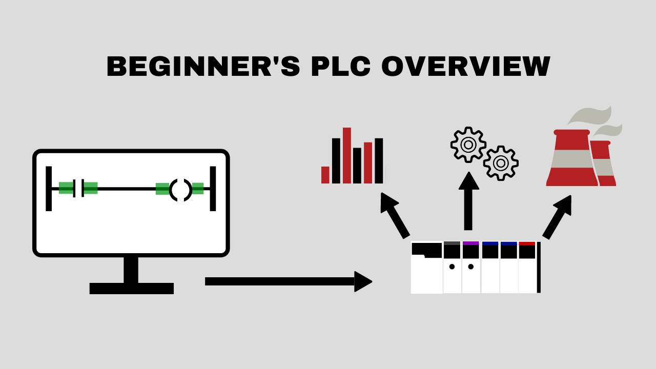
I/O overview
PLC I/O is the part of the PLC that connects the brain of the PLC, the CPU, to the outside world, the machines. In a PLC system there will usually be dedicated modules for inputs and dedicated modules for outputs.
An input module detects the status of input signals such as push-buttons, switches, temperature sensors, etc.. An output module controls devices such as relays, motor starters, lights, etc.
Discrete I/O
The most common type of PLC I/O is discrete I/O. Sometimes discrete I/O is referred to as digital I/O. The concept is simple, discrete I/O are signals that are either on or off. Some examples of discrete input devices would be things like light switches, push-buttons and proximity switches.
 Examples of discrete output devices are lights, relays and motor starters. From our dishwasher example in Part 1, some of the discrete inputs would the start button, the door switch and the water level switch. Some of the discrete outputs would be the water fill valve, the water drain valve and the heating element.
Some specific real-world examples of discrete inputs to a PLC would be open or closed circuit breakers, running or stopped generators, a conveyor belt position sensor, or a water tank level sensor. Some specific applications of discrete outputs would be closing or opening circuit breakers, starting or stopping generators, opening or closing water valves, turning on and off alarm lights, starting or stopping of conveyor belts, etc.
Again, this concept is really simple so I won't belabor it. Just think of discrete I/O as always either on or off. There's no in between. Because of this, discrete signals are simple to process for a computer or PLC. Other ways you can describe a discrete signal are to say it is either true or false, 1 or 0, open or closed.
NOTE: Many people have questions about sinking versus sourcing discrete I/O. Unfortunately this topic causes a lot of confusion. However, the concept is fairly simple. Basic electrical theory says that DC current must flow from DC+ through a load to DC-. You have to have a complete circuit for current to flow, right? Sinking and sourcing just has to with which side of the circuit you are completing to detect your input or activate your output.
The sinking device is the device that's connected to the DC- and the sourcing device is the device that's connected to the DC+ side of the circuit. In the U.S., most PLC/PAC system are designed with sinking input modules and sourcing output modules. This seems intuitive to me; sinking in, sourcing out. If you want to read more about this topic, check out this graphical lesson here.
Analog I/O
The other common form of PLC I/O is analog I/O. Analog I/O refers to signals that have a range of values much greater than just 1 or 0. For instance, an analog signal could produce a voltage anywhere in the range of 0 - 10 VDC. The signal could be 2 V, 3 V, 8.5 V, etc.
In the PLC world, analog input modules usually measure analog inputs in one of the following forms: -10 to 10 VDC, 0 - 10 VDC, 1 to 5 VDC, 0 to 1 mA, or 4 - 20 mA. Basically the analog input module either measures voltage or current from the input device.
There are other types of analog signals but these are definitely the most common. Similarly, the analog output module can supply voltage or current signals in one of the ranges I mentioned previously.
An analog signal that most of us are familiar with is the light dimmer. As you adjust the dimmer knob or slider, the light will get either dimmer or brighter depending on the direction of the adjustment. Similarly an analog input into the PLC can increase or decrease in very small increments and the PLC can produce an analog output that acts the same way.
Some real-world examples of analog inputs in a industrial environment would include engine temperature sensors (RTDs, thermocouples, etc.), oil pressure sensors and weight scales. A temperature sensor might report a temperature range of -50 to 150 degrees C corresponding to 4-20 mA. A weight scale might report a range of 0 to 1000 lb corresponding to 0 to 10V. And so on and so forth.
Analog outputs can be used to control the power output on a generator, the position of a needle on an analog pressure meter, and much more. A 0-3 VDC analog output might be used to drive a generator from 0 - 2000 kW or a 4-20 mA analog output could be used to drive temperature gauge from -20 to 200 degrees F. As you can see there are many possibilities for applications of analog inputs and outputs!
Industrial COMMUNICATIONS
Discrete and analog I/O make up the majority of I/O in most PLC systems. However, one topic I want discuss briefly is communications and the I/O data that can be transmitted or received to/from other controllers and devices via industrial communication protocols. This is a very broad topic, but I want to at least introduce it to you in this post.
There are many industrial communications protocols: Modbus, DNP, BACnet, ControlNet, EtherNet/IP and many more. One of the oldest industrial communications protocols is Modbus. Modbus is still widely used in many devices and PLCs because of its simplicity and its widespread acceptance. It is a good protocol to learn when you're getting started with industrial communications.

Modbus is a master-slave type protocol where one device is the master and all other devices on the Modbus network are slaves. The Modbus master can read from or write to the device depending on the capabilities of the slave device.
So how does this relate to PLC I/O? Many devices such as PLCs, digital meters, SCADA systems, VFDs and genset controllers have been designed with an internal data map of input and output points. The device designer gets to decide how data is allocated.
For instance, in my work I commonly read Modbus data into my PLC/PAC system from power meters so that I can know the kilowatts, voltage, amps, etc on a circuit or generator. In this case the PLC acts as a Modbus master and the power meter is the Modbus slave device. Each device manufacturer will order the data differently in their device's Modbus map, but the communications protocol remains the same.
Master devices can also write data to slave devices. For example, a PLC may be set up as a Modbus master that writes data to start, stop, or change the speed of a Variable Frequency Drive (VFD). If you want to learn more about Modbus check out this video from John Rinaldi at Real Time Automation: Modbus RTU Protocol. John keeps it interesting and fun.
Though all communications protocols work differently they are all designed to do basically the same thing. Industrial communications devices read and write analog or discrete values from and to other PLCs/devices without the need for hardwiring every single input and output point between the PLCs/devices.
NOTE: Most Allen-Bradley PLCs/PACs must use a third-party module or gateway device to communicate via Modbus. There are many of these devices available on the market from companies like Prosoft Technology, Sierra Monitor and Real Time Automation.
As you can see, not only can you connect hard-wired inputs and outputs to your PLC, but you can also read input data from and write output data to devices over Modbus and other industrial communications protocols. This versatility allows most PLCs/PACs to interface with almost any device in an industrial environment.
Conclusion
In this post we looked at discrete I/O, analog I/O and industrial communications protocols. Those three items are responsible for executing all the wishes of the PLC CPU. The CPU looks at data from discrete input modules, analog input modules, and Modbus slaves (or other industrial communications devices). The CPU then performs logic on that input data and activates/deactivate discrete output modules, analog output modules or Modbus slaves.
If you can can put PLC I/O into these three categories in your head (discrete, analog, communications) then you will have a great foundation for knowing how to get data in and out of a PLC.
We've looked at the basics of how PLCs work, the function of the PLC CPU and now the function of the PLC I/O. Next time we will look at how PLCs are typically programmed: Ladder Logic.That's where it gets fun and you start to see how the pieces fit together. So be sure to tune in next time!
In the meantime can you think of any other items than what I listed above that could be PLC I/O? Please share in the comments below!
Was this helpful? Do you have any questions about our online PLC training? As always, we love hearing from you. Let us know what you think in the comments below.
Click here for Part 4 of the Beginner's Free PLC Training Series
P.P.S. Interested in learning more about our online PLC training course for Allen-Bradley PLCs? Check out the Confident PLC Programmer Method course inside myPLCtraining Academy.
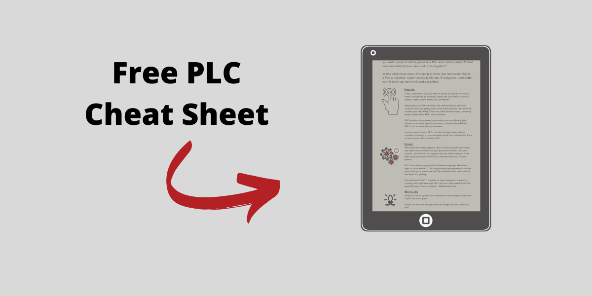
Get the Free PLC Cheat Sheet
PLCs are really not that complicated. If you are new to PLCs or just looking to get a better handle on how they work, check out this free cheat sheet, called the "Motivated Electrician's Guide to Understanding ANY PLC System."


New to PLCs?
You can breeze through this cheat sheet in about 10 minutes and get a solid understanding of the big picture of how PLCs work. Perfect place to start.
Recent Posts