Messaging - How to Get A-B PLCs to Talk to Each Other

This month’s blog post topic is all about sending messages between PLCs. Specifically Allen-Bradley PLCs, such as ControlLogix and CompactLogix controllers.
This is actually pretty cool and a fun topic to learn.
Here’s a simple example of why you’d want to communicate data from one PLC to another.
Let’s say PLC 1 controls one steam boiler and PLC 2 is the main plant PLC that monitors the alarms all the boilers in the plant and other equipment as well.
Think of PLC 2 as the Plant SCADA PLC that allows an operator in the main control room to get an overall look at the plant from his control room.
So let’s say we want to send data from PLC 1 such as the most important boiler temperatures and pressures so that we can display them on the control room HMI screen.
If these are Allen-Bradley PLCs (ControlLogix, CompactLogix), the best way to do this is usually to use Ethernet. Specifically EtherNet/IP.
Here’s a simple image of how the two PLCs would likely be physically connected with an Ethernet network.
With Ethernet, usually if you have multiple devices on a network, they all connect to a "hub" called an Ethernet switch.
There are many different options for communications networks that PLCs may need to talk, but Ethernet is, by far, the most common for new systems.
There are a couple different ways that we can configure Allen-Bradley PLCs can talk to each other. The way we will focus on in this months newsletter is using MSG (message) instructions.
Here’s what a MSG instruction looks like in Studio 5000 Logix Designer...
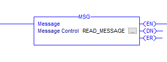
And here’s what it looks like on the inside on the MSG configuration. Looks complicated right?

Looks complicated, right?
To be honest, I’ve only used 3 or 4 of the of the different message types, so don’t worry, you don’t need to learn all of them.
Ok, that's what a MSG instruction looks like. Let's dig into how to set it up.
LOGIX MESSAGING (MSG)
Prefer to read it? Go Ahead…
Hey guys, it’s Stephen Gates here from myPLCtraining.com with another PLC training video to help you become a confident PLC programmer.
Today’s video is cool because you’re going to learn exactly how to set up communications between two ControlLogix PLCs AND if you have access to Studio 5000 Logix Designer and Logix Emulate you will actually be able set up communications between two Emulate controllers today and test it out.
Which, be the way if you do NOT have access to Studio 5000 Logix Designer and Logix Emulate but you’re serious about learning PLCs, then you absolutely should join myPLCtraining Academy where we give you access to our own Studio 5000 software licenses.
It’s absolutely the best PLC training offer on the internet right now.
Ok, so back to the topic at hand. Here we are in Studio 5000 Logix Designer and we are going to start by adding a rung. Next, let’s go to the Input/Output instruction tab and grab the MSG instruction.
Now first things first, we will need to assign a tagname to the MSG instruction. I’m going to call it CIP_READ_MSG.
Ok, now the configuration window pops up and so from here we will need to set up the rest of the message configuration.
So first of all, we need to choose the message type. We are only going to focus on two message types in this video, but just to give you an idea, there are different types of instructions for talking to different devices or across different networks.
So for example, we have PLC5 type messages and SLC type messages and even PLC2 messages which are are super old PLCs that came before the PLC5
But again for this video we are only going to focus on two types of messages. The CIP Data Table Read and CIP Data Table Write.
Now we're going to go through the whole setup for talking between two different Emulate Controllers, but everything except the communication path would be the same for talking between two ControlLogix controllers.
If you want more details on setting up messages between ControlLogix or CompactLogix controllers then check out the free bonus lesson coming up.
So, for this message, we are going to set it up to read tags from a second controller. So we will choose CIP Data Table Read.

And just to clarify using my super fancy drawing, picture setting up our message instructions inside PLC 1 to talk to PLC 2. Even though we are going to be talking between two emulator controllers, the setup will be basically the same as it would be for talking between two ControlLogix controllers.

Ok, so now we have the 3 fields we need to fill in here. The source element this will be the tag name from the controller we are reading from.
Then the number of elements we are reading, so if it’s a tag array inside the source controller we can choose how many elements of the array we want to read.
And then we have the destination element which is where we put the tag name inside this controller that we want to put the data in that we read from the other PLC.
Ok, in this example, I’ve got an array of DINT tags in PLC 2 that is called PRODUCE_DATA and we start that at element 0 of that array.

We are going to gather 10 elements from that array so we set “Number of Elements” to 10.

Next, we have the destination element which will be the name of the tags inside PLC 1 which is the PLC we are configuring. So this we will call this CONSUME_DATA and starting at element 0, so CONSUME_DATA[0]

And if this tag array hasn’t been created yet you can just click this handy “New Tag” button.
Ok, so we are going to read 10 elements of the PRODUCE_DATA array from PLC 2 and place it into the first 10 elements of the CONSUME_DATA array in PLC 1. Now let’s go to the communication tab to make sure that this message reaches PLC 2.
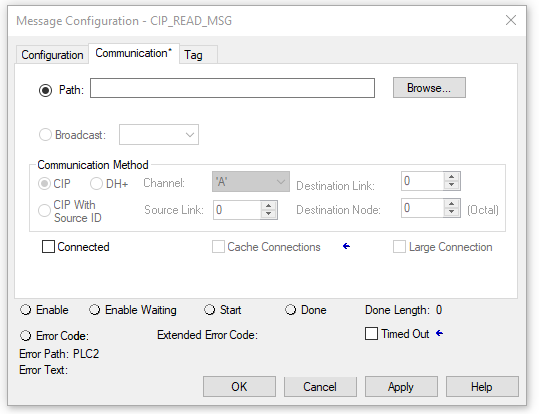
Ok so here we are on the communication tab and the path is empty.
So we need to click the Browse button and choose the controller we want to talk to. As you can see I’ve set up PLC_2 in slot 1 of the same chassis as PLC_1
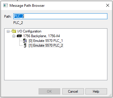
So let’s choose PLC_2 and click Ok.
Ok, now one more thing before we are ready to test our message instruction.
The MSG instructions only run once when the rung is true. So if we want it to continually run we need to create logic that resets the rung continually.
The easiest way to do that if you have relatively small or simple program is to just use the .EN bit of the MSG itself. So that looks like this.
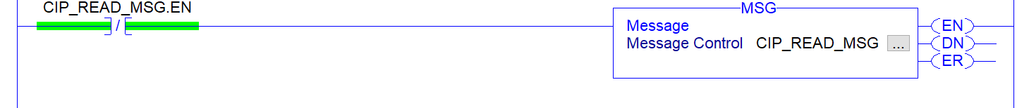
That will reset the rung over and over so the instruction will continually execute.
Ok so now we will download our PLC_1 project to it’s controller and our PLC_2 project to it’s controller.
Now, we can see the MSG instruction .DN bit is going true so the communication is working.
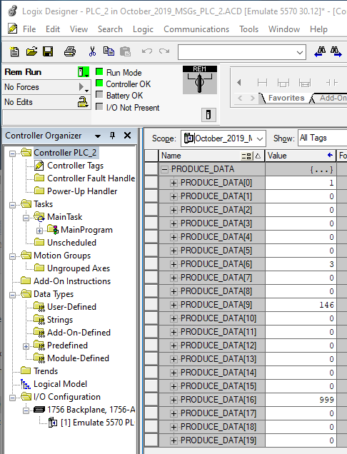
So, when we update the PRODUCE_DATA array in PLC_2 it should be reflected in PLC_1
Notice that updating the PRODUCE_DATA[0] in PLC_2 is updating the value in CONSUME_DATA[0] in PLC_1
And likewise all the elements from 0-9
But if we update an element in PRODUCE_DATA beyond element 9 then it won’t update in CONSUME_DATA because we are only reading 10 elements.
See PRODUCE_DATA[16] is 999 but CONSUME_DATA[16] is still 0

Ok, that’s it for this PLC training on sending messages between Allen-Bradley controllers.
I hope you found this helpful! Stay tuned for a free bonus lesson on MSG instructions for communicating between ControlLogix controllers via ethernet.
We will see you in the next video!
Get the Free PLC Cheat Sheet
PLCs are really not that complicated. If you are new to PLCs or just looking to get a better handle on how they work, check out this free cheat sheet, called the "Motivated Electrician's Guide to Understanding ANY PLC System."


New to PLCs?
You can breeze through this cheat sheet in about 10 minutes and get a solid understanding of the big picture of how PLCs work. Perfect place to start.
Recent Posts